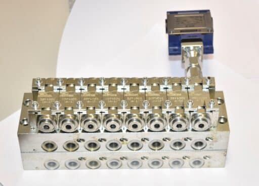
Series 3117XX3XX
Single line air-oil dosing valve
Serial 3117XX3XX
Features
| Max. Air pressure | 10 bar |
| Min. Air pressure | Output pressure + 1 bar |
| Max. Oil pressure | 45 bar |
| Min. Oil pressure | Output pressure + 20 bar |
| Oil discharge pressure | < 1,2 bar |
| Fluid | Mineral oil |
| Viscosity | Up to 3000 cSt. Depending on temperature |
| Range of temperature | -20ºC. / +80ºC. |
| Max. Oil Viscosity to operate at 5ºC | ISO VG 100 |
| Air inlet | 1/4”bsp |
| Oil inlet | 1/4”bsp |
| Outputs | 1/8”bsp |
Aplication
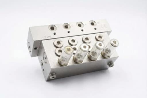
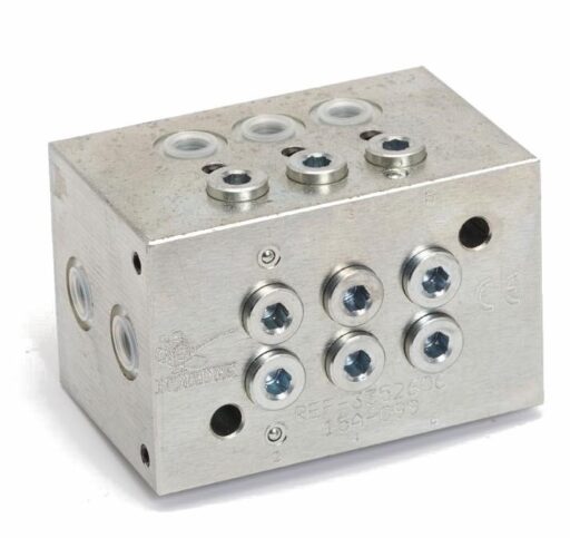
Single line air-oil dosing valves are suitable for low viscosity oils and for high-speed bearings installations.
Design and operating principle
Each dosing valve group (Fig. 1) is composed of the mixing block “1” and the dosing element “2”. The dosing element is responsible for distributing the lubricant towards the block where the mixture is done which is then directed to the outlet, each outlet has an air adjustment screw “3”, to adjust the required volume of compressed air.
Outlets that are not necessary can be plugged with a plug “4” Nortek 5060120. Oil pressure at the inlet of the dosing valve is fluctuating, therefore when the pulses occur, the piston moves due to the pressure in the prechamber, then the oil contained in the chamber is inyected into the dosing valve. By contrast when the feeding pulse is zero, the spring of the dosing chamber moves the plunger allowing to transfer the oil from the prechamber to the chamber of the dosing element, starting the cycle again.
Installation
Pararell installation
This is the most common installation, the dossing valves are connected independent to the main line. It is necessary to drill the closing air cap to purge condensed water of the installation and avoid an incorrect greasing.
Series instalation
This installation is recomended, depending on number of the dosing valves installed, due to pressure drop and the space available for the installation
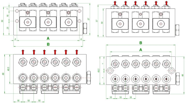
Dimensional drawing
Order information
The standard supply corresponds to the dosing valve with 6 outlets.
The reference is formed depending on the number of outlets and their position. The last digit is indicated depending on the volume required at the exit (volume of the dosing element), as show in the following table.
| LETTER TO ADD ACCORDING TO THE SIZE OF THE DOSING VALVE |
| 3117 XX 3 X X |
| Nº outlets
|
| 02 |
| 04 |
| 06 |
| 08 |
| 10 |
| Position of the outlets |
| Upper 0 |
| Back 2 |
| Volume at the exit (cm³) |
| 0,022 A |
| 0,034 B |
| 0,057 C |
| 0,110 D |
| 0,230 E |
Other products
We will get back to you within 24 hours
Do you have any questions? Are you ready to buy? Your Nortek assistant is ready to help you
Success stories
We are your reliable partner to make everything flow and nothing stands still.
Leave the fluid management of all your machines in our hands so that they always work at 100%, increase their performance and extend their service life. It’s time to stop worrying about the performance of your machinery.
Discover how our solutions have delivered great results
