Series 103852X
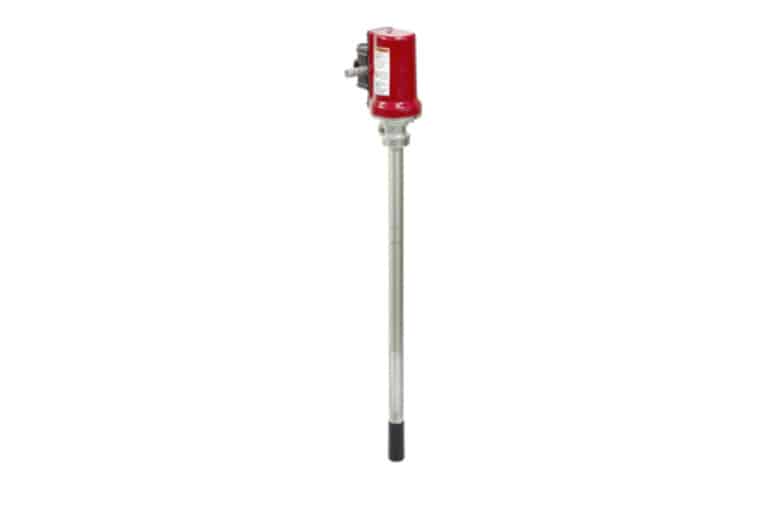
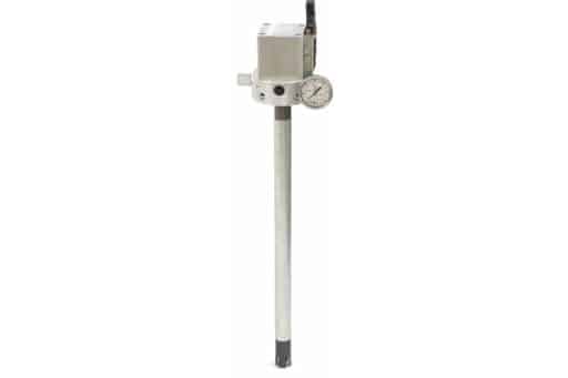
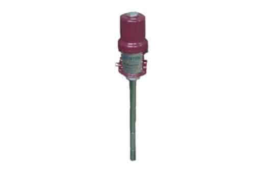
Pneumatic pump mounted on drum BN50
These pumps are designed to work with grease and oil, whatever environment, The main application of the 5: 1 pump is as an oil transfer pump and the 50: 1 model as lubrication in pneumatic installations.
PDF files
Features
- Air inlet filtered
- Low air consumption
- For grease and oil (see ranges)
- Available with standard drum rods 60 Kg and 200 Kg
- Modular air valve
Description
Two models of high pressure pumps, one for a medium flow of oil with a ratio of 5: 1 and the other for grease with a ratio of 50: 1, both complement each other perfectly for a wide range of lubrication.
Each model has its configuration for 60 and 200 kg tanks.
Design and operating principle
Operation is similar to most of the double action piston pumps. The pump only comes to a complete stop on the up stroke. The pump will stroke through on the down stroke due to the inlet check relief passage.
Excess pressure due to downstream thermal expansion causes the air motor/pump to run backwards (downward). Fluid pressure is relieved through the inlet check relief passage (b) as the pump piston moves downward. Air pressure is simultaneously relieved through the air inlet passage. The pump piston moves downward exposing the pump cylinder relief passage (a) at the bottom of the stroke. Additional excess pressure is then relieved through both the inlet check relief passage (b) and the pump cylinder relief passage (a).
The pump will not change over on the bottom of the stroke as a result of relieving excess pressure due to the positioning of the pump cylinder groove with respect to the air motor pilot valve.
Installation
The typical installation shown, is only an installation guide. It is not an actual system design.
Key
- A – Fluid outlet line (flexible connection required)
- B – Pump
- C – Ground wire
- D – Pump runaway valve
- E – Air lubricator
- F – Bleed-type master air valve (required)
- G – Air regulator (self-relieving regulator required)
- H – Air filter
- J – Main air line
- K – Bung adapter
- L – Fluid inlet line (flexible connection required)
- M – Air inlet line (flexible connection required)
In case of mounting on a drum, it is possible to install a return rod on the pump (Ref. 1038524.000) through which all the excess grease from the installation can be returned.
To reduce the risk of static sparking, ground the pump and all other components used or located in the dispensing area.
Specifications
| Oil | Grease | |
| Ratio | 5 : 1 | 50 : 1 |
| Maximum working pressure | 51,7 bar | 517 bar |
| Recommended air pressure | < 8,6 bar | < 8,6 bar |
| Recommended maximum speed | 180 cycles/minute | 120 cycles/minute |
| Air inlet | G 1/4 | G 1/4 |
| Grease outlet | G 1/2 | G 1/4 |
| Flow | 25 L/min | 1,87 kg/min |
| Approximate weight | 3,5 kg. | 5,1 kg. |
Order information
| ADD CODE DEPENDING ON ASSEMBLY | |||||||
| BN50- | X | XXX | X | X | X | (-XX) | |
| Lubricant | |||||||
| Oil (Pump ratio 5:1) | A | ||||||
| Grease (Pump ratio 50:1) | G | ||||||
| Drum | |||||||
| Drum 60 litres | 060 | ||||||
| Drum 200 litres | 200 | ||||||
| Return rod | |||||||
| Without return rod | N | ||||||
| With return rod | C | ||||||
| Drum cover | |||||||
| Without drum cover | N | N | |||||
| With drum cover | T | ||||||
| Minimun level indicator | |||||||
| Without minimun level indicator | N | ||||||
| With minimun level indicator | I | ||||||
| Special code | |||||||
| For non-standard elements | (-XX) | ||||||
Other products
We will get back to you within 24 hours
Do you have any questions? Are you ready to buy? Your Nortek assistant is ready to help you
Success stories
We are your reliable partner to make everything flow and nothing stands still.
Leave the fluid management of all your machines in our hands so that they always work at 100%, increase their performance and extend their service life. It’s time to stop worrying about the performance of your machinery.
Discover how our solutions have delivered great results


