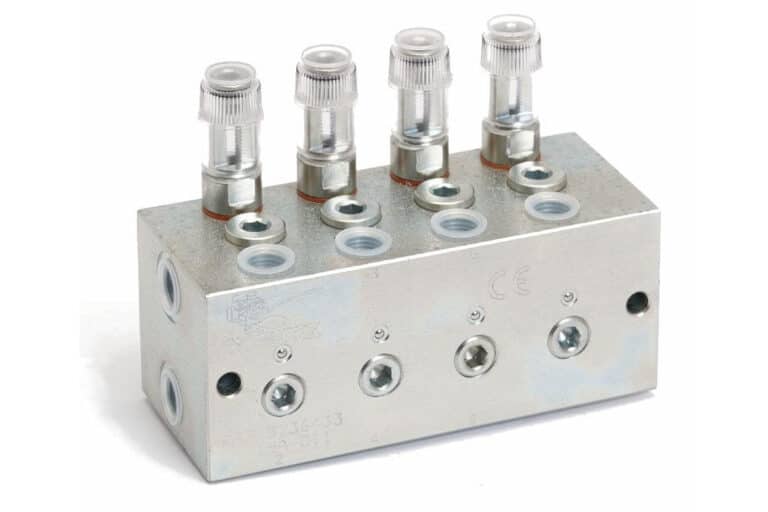
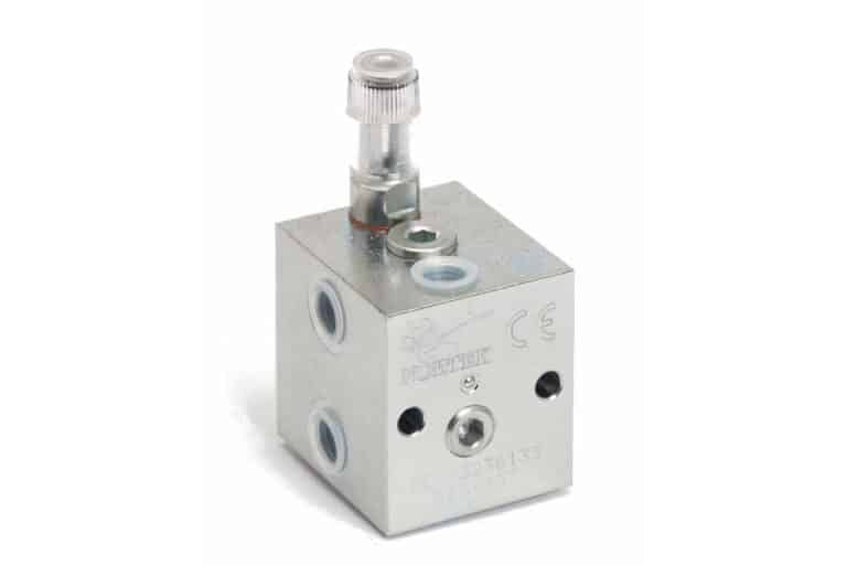
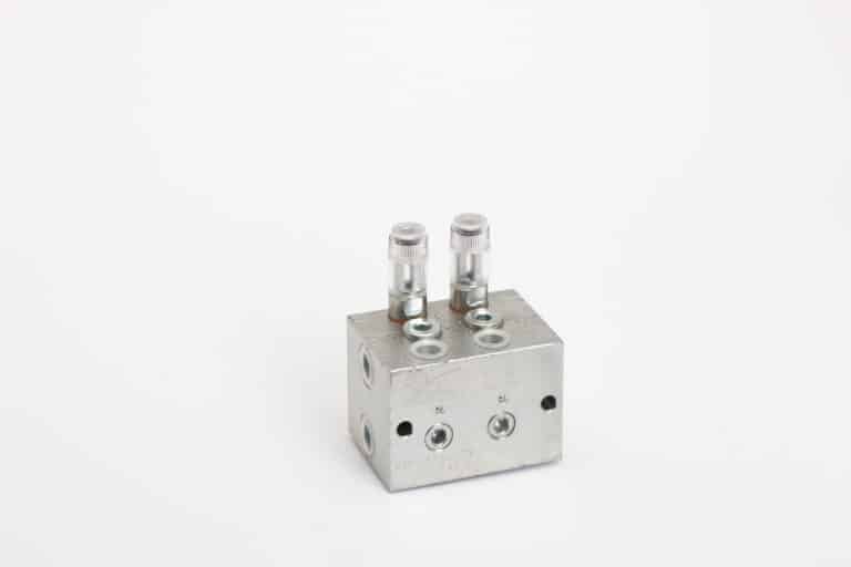
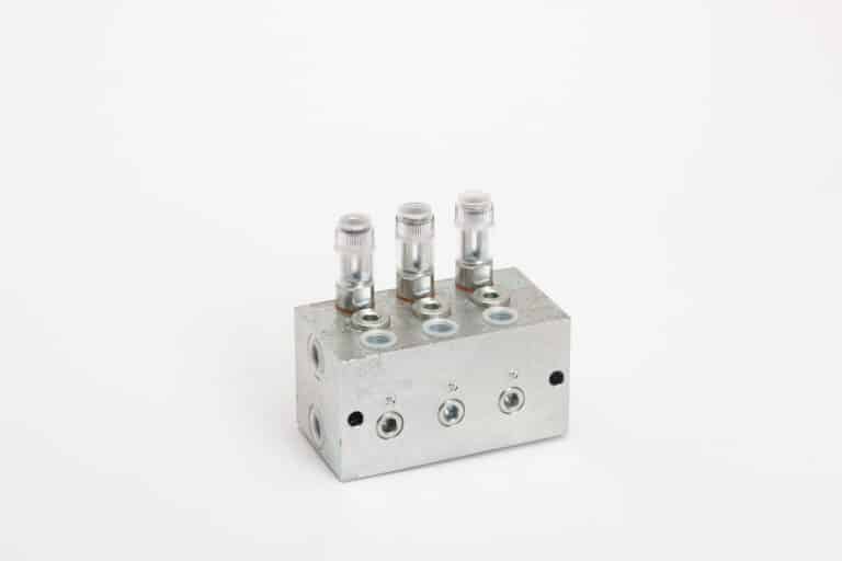
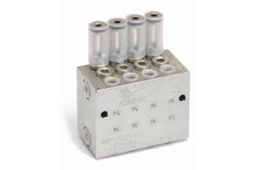
Series 3236033
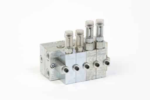
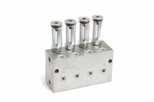
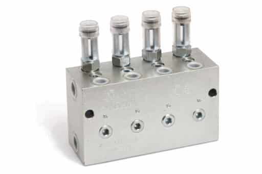
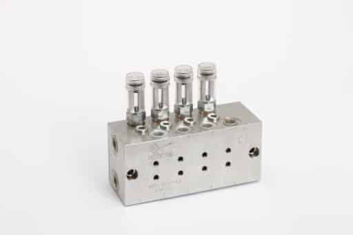
Dosing valve D12
These dosing valves are normally placed in double lines of oil or grease and are intended for installations that include a large number of greasing points and / or long distance.
Installations in the steel industry, cement or paper mills it is possible to use this type of dosing valves with high guarantees of precise lubrication.
PDF files
Features
- Design in block avoiding leaks
- Oil or grease can be used
- High performances
- Possibility of different turrets for operation, visual or electrical control by means of micro or proximity detector.
- Possibility of armored turret
- Robust steel body according to EN 10087-11SMnPb30
- Adjustable flow
- Caps available in methacrylate, nylon or aluminium.
Description
The dosing valves are lubrication elements installed for two simultaneous supply lines, one of them pressurized while the other is depressurized, alternating the greasing cycles, in this way is supplied an adjustable amount of lubricant in each cycle.
Design and operating principle
Each dosing valve is composed of a servo piston (A) and a servo (B). The piston movements (Fig. 1) show the operation of the dosing valve by alternating the lubricant supply when it enters line 1 or when it enters line 2.
The supply is made with the two separate outputs, but there is the possibility of internal communication of the outputs unifying in a single output, thus doubling the flow. It has two possibilities, through internal or external communication.
- Internal communication is done online, opposite outputs are communicated, it consists of removing the plug (C) and removing the ball from its interior (D). (Fig. 2)
- External communication, outlets can be joined in line and it is carried out by means of two extra pieces in its exterior, the union block (F) and the warhead (E). (Fig. 3)
Being the internal communication we offer the advantage of avoiding fittings and external pipe, thus favoring a clean installation.
Installation
They are placed in double lines throughout the installation in the areas closest to the greasing area. The quantity of dosing valves to be installed depends on the length of the installation and the points to be greased.
Installation dosing valves in line 1
The grease or oil coming from the pump through line 1 is pressurized in the valve; it moves the servo, giving way to the injector, which moves it in the same direction, fills the entire chamber with lubricant and at the same time injects the lubricant stored on the opposite side to the lubrication point.
Installation dosing valves in line 2
When all the pistons of the installation have moved, the pump and inverter pressure reaches the one that was regulated and determined, then changes the inverter to line 2 and leaves line 1 in return, where the pressure drops to zero. The pump through line 2 introduces the lubricant into the dosing valve and moves the injector by lubricating on the opposite side.
Specifications
| D06 | D12 | D15 | D23 | D50 | |||||
| Nº outlets | From 2 to 8 outlets | ||||||||
| Max. flow rate per injection (adjustable) | 0,6 cm3 | 1,2 cm3 | 1,5 cm3 | 2,3 cm3 | 5 cm3 | ||||
| Minimum working pressure | 10 bar | ||||||||
| Maximum working pressure | 250 bar | ||||||||
| Input connections | G 1/8 | G 1/4 | G 3/8 | G 3/8 | G 3/8 | ||||
| Output connections | G 1/8 | G 1/4 | G 1/4 | G 1/4 | G 1/4 | ||||
| Qualities | Electroplated coating of zinc ISO 2081 – Fe/Zn12/A | ||||||||
| Weight | |||||||||
| 2 outlets ( 1+1 ) | 0,4 kg | 1,1 kg | 1,7 kg | 1,5 kg | 1,6 kg | ||||
| 4 outlets ( 2+2 ) | 0,6 kg | 1,7 kg | 2,3 kg | 2,6 kg | 2,7 kg | ||||
| 6 outlets ( 3+3 ) | 0,8 kg | 2,3 kg | 2,9 kg | 3,7 kg | 3,8 kg | ||||
| 8 outlets ( 4+4 ) | 1,1 kg | 2,9 kg | 3,6 kg | 4,8 kg | 4,9 kg | ||||
Order information
The standard supply is simple turret with body in EN 10087-11SMnPb30 with electroplated coating of zinc according to ISO 2081 – Fe / Zn12 / A, methacrylate cap, NBR seals and body in AºCº
| ADD LETTER DEPENDING ON ASSEMBLY | ||||||
| XXX- | X | X | X | X | (-XX) | |
| Series | ||||||
| Dosing valve: max. flow rate per injection 0,6cm3 (adjustable) | D06- | |||||
| Dosing valve: max. flow rate per injection 1,2cm3 (adjustable) | D12- | |||||
| Dosing valve: max. flow rate per injection 1,5cm3 (adjustable) | D15- | |||||
| Dosing valve: max. flow rate per injection 2,3cm3 (adjustable) | D23- | |||||
| Dosing valve: max. flow rate per injection 5cm3 (adjustable) | D50- | |||||
| Outputs | ||||||
| 2 outputs (1+1) | 2 | |||||
| 4 outputs (2+2) | 4 | |||||
| 6 outputs (3+3) | 6 | |||||
| 8 outputs (4+4) | 8 | |||||
| Turrets | ||||||
| Normal | N | |||||
| Electric | E | |||||
| Blind | C | |||||
| Without turret | S | |||||
| Aluminum cap | A | |||||
| Seals and gaskets | ||||||
| NBR | N | |||||
| Viton | V | |||||
| Material | ||||||
| Carbon steel – 11SMnPb30 | C | |||||
| Stainless steel – X5CrNiMo17-12-2 (AISI-316) | I | |||||
| Special code | ||||||
| For non-standard elements | (-XX) | |||||
Other products
We will get back to you within 24 hours
Do you have any questions? Are you ready to buy? Your Nortek assistant is ready to help you
Success stories
We are your reliable partner to make everything flow and nothing stands still.
Leave the fluid management of all your machines in our hands so that they always work at 100%, increase their performance and extend their service life. It’s time to stop worrying about the performance of your machinery.
Discover how our solutions have delivered great results
