Series Serie 3290153
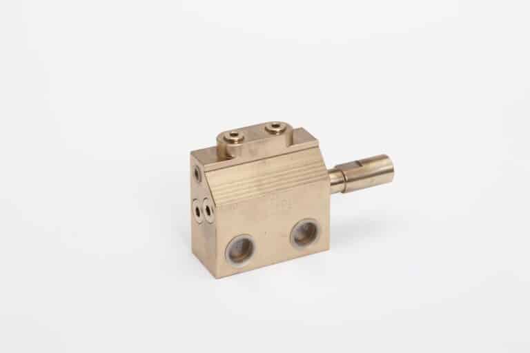
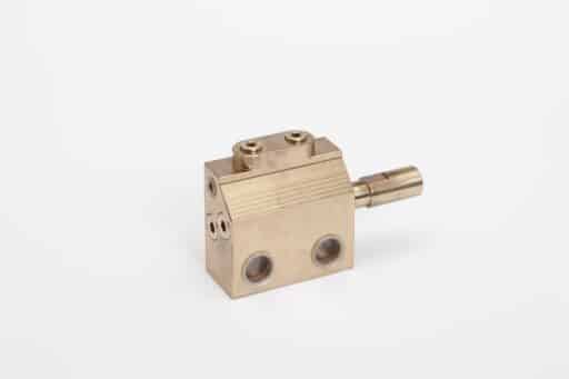
Naval dispenser 3 cm3
PDF files
Serie 3290153
Features
- Block design to avoid leakage.
- Usable with grease and oil.
- Made of highly corrosion resistant material.
- corrosion.
- Adjustable flow rate.
Aplication
Lubrication of all elements where the metering unit is in contact with water.
the dispenser is in contact with sea water: dredgers, submarines marine: dredgers, submarines, etc… in general any type of lubrication in the naval industry.
Design and operating principle
Designed in aluminum alloy and bronze EN 1982 – CuAl10Fe5Ni5-C resistant to marine waters in the worst conditions, even the most oxygenated surface waters. Conditions, even those of surface waters which are much more oxygenated. Each dosing dosing unit is composed of a servo piston (A) and a
servo piston (A) and a servo (B). The movements of the piston movements illustrated in Fig. 1 show the operation of the dosing unit alternating the
feeding of the lubricant when entering through line 1 or when it enters through line 2.
The supply is made with the two separate outlets, but there is the possibility of internal communication of the outlets, unifying them into a single outlet, thus doubling the flow rate.
the outlets unifying them in a single outlet, thus doubling the flow rate. The internal communication offers the advantage of avoiding
advantage of avoiding external piping and fittings, thus favoring a clean installation.
Description
Dosing units are lubrication elements designed for two simultaneous supply lines, one being pressurized and the other depressurized, one of them being pressurized and the other depressurized. The lubrication cycles are alternated
thus dispensing an adjustable amount of lubricant in each cycle.
Installation
They are placed in double lines along the entire installation in the areas closest to the greasing zone. The number of dispensers to be installed depends on the length of the installation and the points to be greased.
Metering system line 1
The grease or oil coming from the pump through line 1 is pressurized into the valve; it displaces the servo, leaving a passage towards the injector, the servo, leaving a passage to the injector, displaces the injector in the same direction, fills the entire chamber with lubricant and at the same time injects the stored lubricant on the side chamber and at the same time injects the lubricant stored on the opposite side to the lubrication point.
Dosing system line 2
When all the plungers of the installation have moved, the pressure in pump and inverter reaches the pressure that was set and determined, then the inverter switches to line 2 and leaves line 1 in return, where the pressure drops.
then switches the inverter to line 2 and leaves line 1 in return, where the pressure drops to zero. The pump through line 2 introduces the lubricant into the metering valve and displaces the injector and lubricates the opposite side.
Specifications
| No. of outlets | 4 ( 2 + 2 ) |
| Outlet flow per injection | 3 cm3 |
| Minimum working pressure | 10 bar |
| Maximum working pressure | 250 bar |
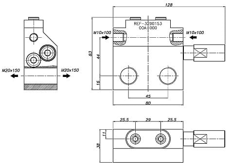
| Inlet connections | M10x1 |
| Outlet connections | M20x1.5 |
Dimensional drawing
Order information
| Specifications | Weight | Reference |
| Naval dispenser 3 c.c. 4 outputs( 2+2 ) | 1.3 kg | 3290153 |
Other products
We will get back to you within 24 hours
Do you have any questions? Are you ready to buy? Your Nortek assistant is ready to help you
Success stories
We are your reliable partner to make everything flow and nothing stands still.
Leave the fluid management of all your machines in our hands so that they always work at 100%, increase their performance and extend their service life. It’s time to stop worrying about the performance of your machinery.
Discover how our solutions have delivered great results


